Electric Motor Repair Case Study – 9000HP Boiler Feed Pump Motor – Repairs Taken & Results
November 1, 2016
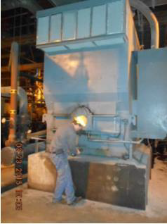
The results of the “on-site” findings in conjunction with the “in-shop” inspection led to the electric motor repair approval to build a new rotor assembly for this Boiler Feed Pump Motor (9000HP, 1800RPM, 13,200v, Siemens Allis).
This is the third article in a series of articles on this Boiler Feed Pump Motor case study. Articles will be released over 3 consecutive weeks. This article focuses on the repairs taken while the motor was at the repair facility. The first article was based on the “on-site” findings that gave the justification required to pull the motor for repair. The second article showed was was found once the motor was dismantled/inspected in the motor repair shop.
Rotor Repair Steps/Items:
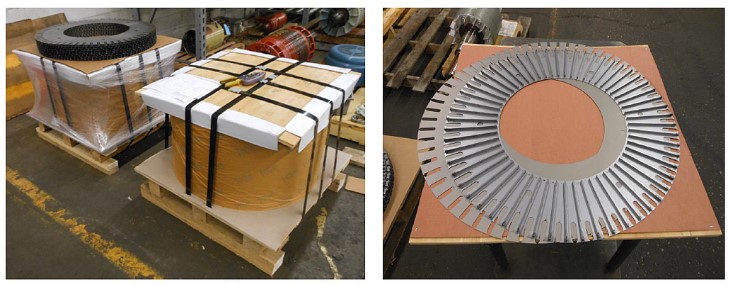
Upon receipt of the approval to proceed with the repairs and the manufacture of a new rotor while utilizing the existing shaft/spider assembly, Laser cut C-5 core material was designed and purchased.
The old rotor was disassembled and a mandrel was made to stack the lamination onto.
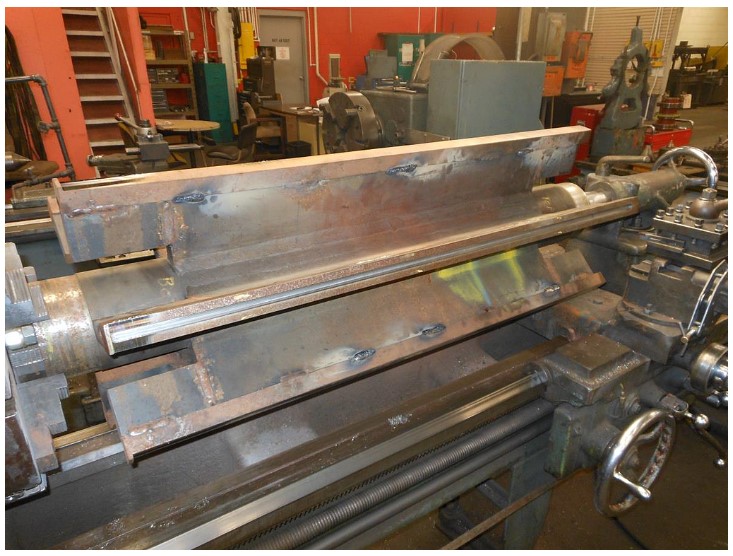
Rotor laminations were then stacked onto the mandrel.
While the laminations were being made/stacked, the new shorting/end rings were machined on an indexing table to allow for the new rotor bars.
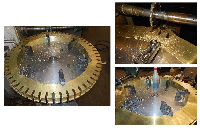
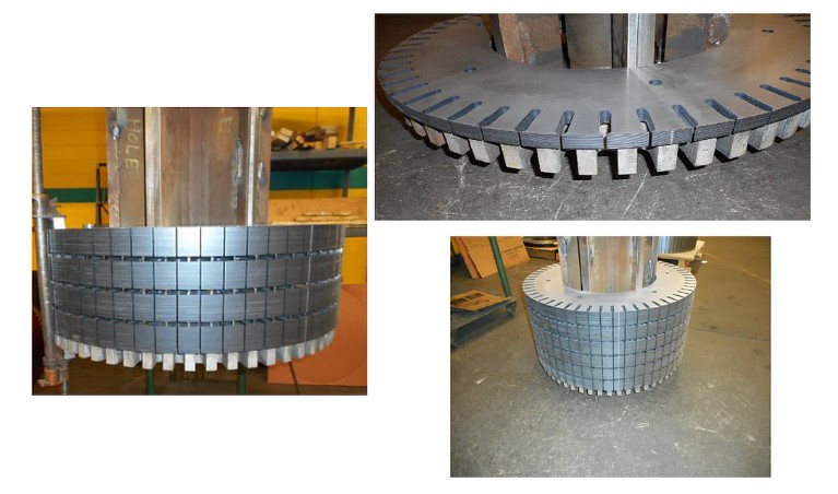
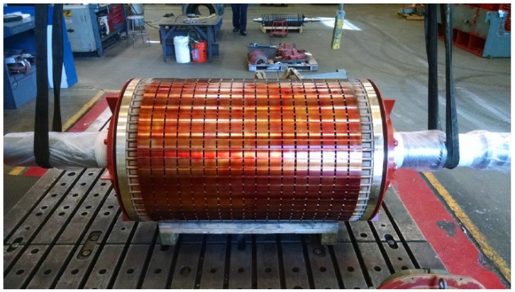
Rotor Bars were then fitted and installed into the lamination stack. The stack is then compressed. The slotted end rings and rotor bars are brazed together using silver solder.
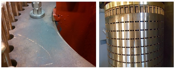
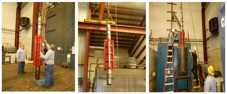
The shaft was then prepared and the rotor stack is heated for expansion in a large oven. After the rotor has expanded to the desired size, the shaft is then lowered into the stack.
After the rotor cools down, the O.D. (Outer Dimension) of the rotor is then turned true to the shaft and to the proper diameter for the desired air gap between the rotor O.D. and the stator I.D. (Inner Dimension)
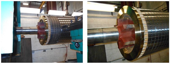
After cleaning, the rotor is coated with a lamination coating. The rotor cooling fans are then installed and the complete rotor assembly is balanced to the customer’s required standards.
Other Repaired Items
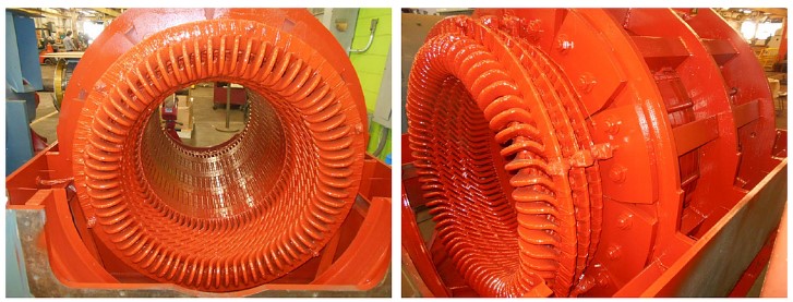
While the new rotor was being manufactured, there were some other items that required repair on this unit. During the initial inspection the stator was plugged full of dirt/debris. The stator required a good cleaning/baking process and some of the winding’s blocking was cracking and had to be replaced/repaired.
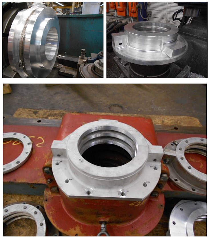
It was also identified on the incoming inspections that the bearing housing seals were out of tolerance. Since this motor was a vintage design, replacements could not be purchased. Therefore, replacement seals were manufactured in HECO’s machine shop.
Final Test Run
After all the repairs were completed, the motor was re-assembled. It was then placed on HECO’s isolated test bed and tested at full nameplate voltage until bearing temperatures stabilized. An oil feed system was utilized to simulated the lubrication system at the plant.
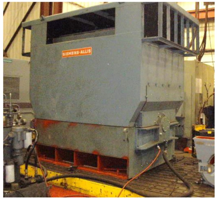
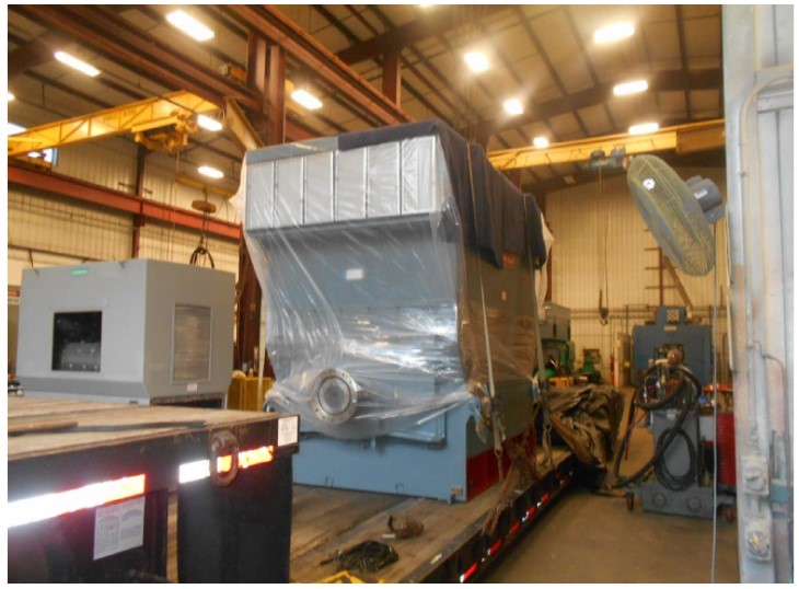
The motor passed all of HECO and the customer’s final testing requirements. The motor was then painted and loaded onto a tractor trailer and returned to service.
Repair Results
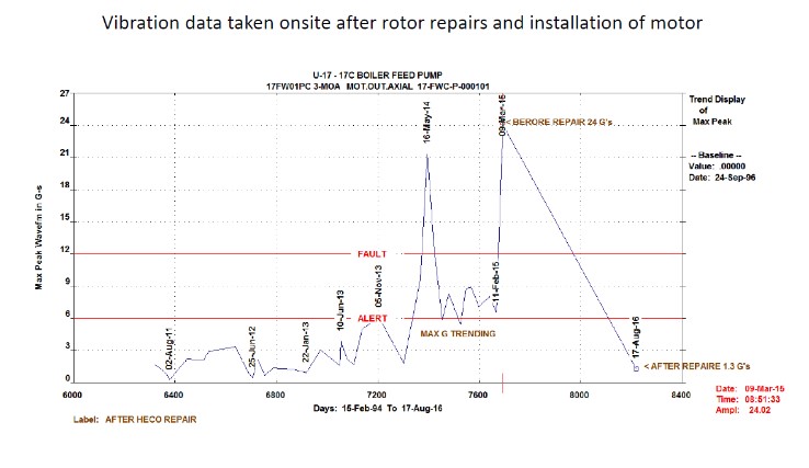
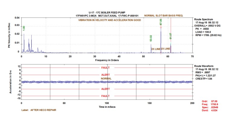
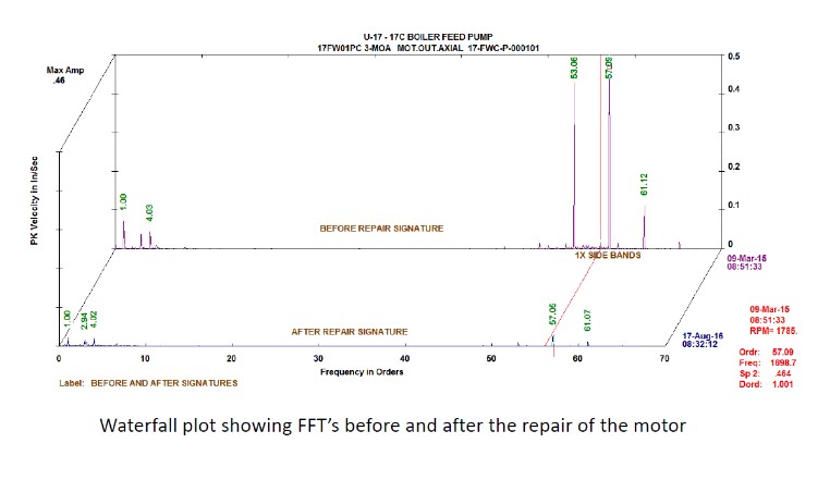
The motor was immediately returned to operation at it’s original location. Below is the vibration trend and then analysis data showing the results and success of the repairs taken.
Long Term Preparations/Thoughts
Upon further analysis, it was identified that there were a variety of these motors installed at the customer’s location. Since all the machines were of the same vintage and design, the sister units needed to be monitored for similar issues.
This repair was a success as it was caught “in-time” – the end users reliability/predictive group worked with the repair shop to identify the issues and caught them before it caused a catastrophic failure. If the rotor would have completely failed in-service it could have caused serious issues with the motor’s stator causing a rewind or even worse damaging the core of the stator as well.
Due to the nature of the issue – vibration testing has been enhanced and performed more frequently in the past. Regular and routine testing/inspections are being performed to avoid a catastrophic failure on any of the other 5 units that have the same design as this unit.
Posted in Repair