Methods of Detecting Cracked Rotor Bars in Electric Motors
August 11, 2016
Before reading about these different tests, please check out our last few articled on electric motor theory and rotor bar cracks:
Besides a simple visual inspection, below is a summary of the most common methods of detecting cracked rotor bars as well as shorted laminations in an induction electric motor’s rotor. Many of these tests need to be done in an electric motor repair shop.
GROWLER TEST – This test is performed with the rotor out of the stator. Current flow is induced through the rotor by energizing a laminated core wrapped with wire and placing this core close to the rotor. The rotor bars are magnetized and by the use of iron filings/hacksaw blade you determine a discontinuity of current flow through a rotor bar or a cracked bar. Test works best with a heated rotor.
SINGLE PHASE ROTOR TEST – This test is performed while the motor is still together. Single phase power is (low voltage, several amps) applied to the motor as the rotor is slowly rotated. An analog meter is monitoring one leg (phase) looking for any fluctuation in amp draw. If the stator current lowers or decreases it is a sign of one or more cracked rotor bars. Again this test is best performed with the rotor heated.
HIGH CURRENT ROTOR TEST – This test is performed by applying high current through the shaft of the rotor (rotor out of stator) and thermally scanning (infrared or thermoscan) the rotor O.D. searching for shorted laminations. These shorted laminations cause localized hot spots which cause uneven heating of the rotor. This causes the rotor to bow and go out of balance. This localized heating can also cause stress to the bars and premature bar cracking and fatigue. This test will also identify a loose rotor to shaft interference fit.
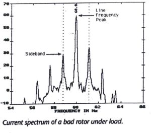
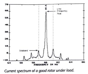
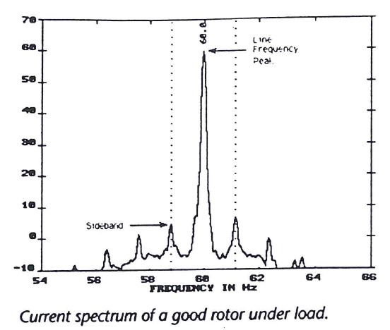
INDUCTION MOTOR CURRENT ANALYSIS (CURRENT SPECTRUM TEST) – This test is performed while the motor is under 50 – 100% load. The rotor induces currents back in the stator windings. These currents appear as side bands around the supply line frequency (60 HZ) peak, and are a function of the motors number of poles and slip frequency. By comparing the sideband amplitudes, you can estimate the number of broken rotor bars. This test is the most accurate and reliable.


VIBRATION SPECTRUM ANALYSIS – This test can detect cracked or loose bars while under load. Under load, the vibration will modulate at a rate equal to the number of poles times slip frequency. With a broken rotor bar, the amplitude of the beat increases with load. A cracked rotor bar can also cause localized heating of the rotor which causes uneven expansion and rotor bowing. This results in an unbalance and a strong 1 times running speed vibration as well as the side bands related to slip frequency. Loose rotor bars may give similar symptoms and also will show vibration at rotor bar passing frequencies. This test will not show up at no load running because a broken rotor bar can not carry current. When it is in an area of high flux, the magnetic forces on the rotor are unbalanced. Since the current flow through the rotor bar is proportional to slip, at no load when rotor current is low, the bar has virtually no magnetic forces acting on it.
Posted in Equipment Management, Predictive
